So I’ve been neglecting my own projects lately while I’ve been working on competitions for my hackerspace.
Here’s on of the finished products, the Hammer Slammer for Red Bull Creation contest.
So I’ve been neglecting my own projects lately while I’ve been working on competitions for my hackerspace.
Here’s on of the finished products, the Hammer Slammer for Red Bull Creation contest.
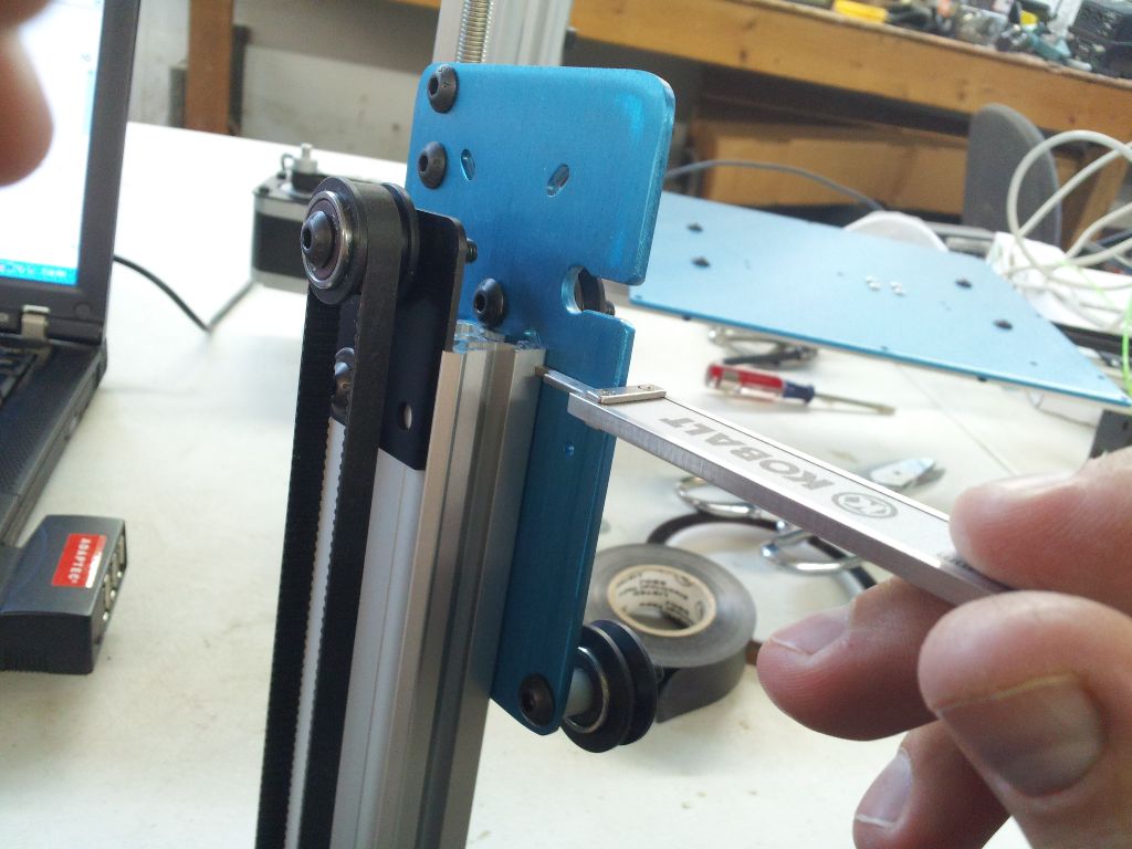
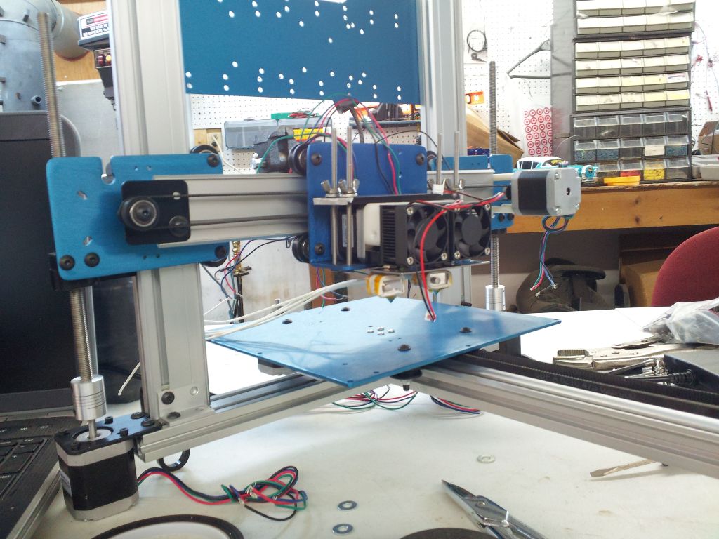
So I finally made some time late at night to work on my ord bot. First thing I did was try to true up some of the brackets, make sure everything is straight and tight.
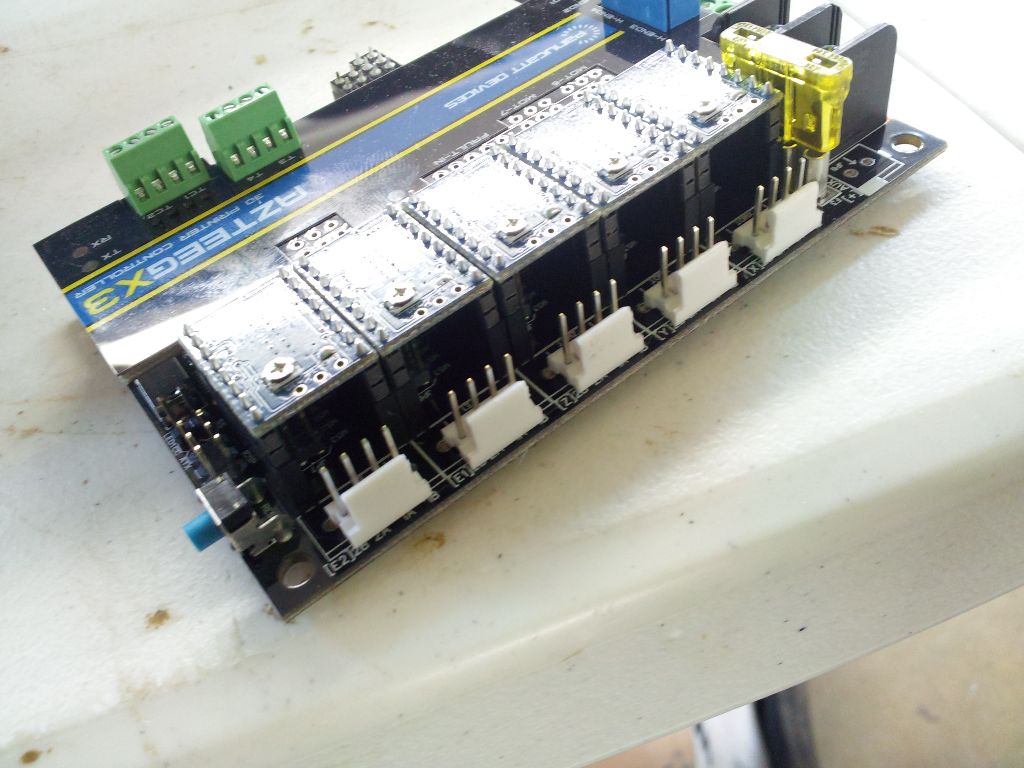
Next I went ahead and soldered the stepper headers onto the azteeg x3, I decided this look was cleaner than going with the screw terminal approach.
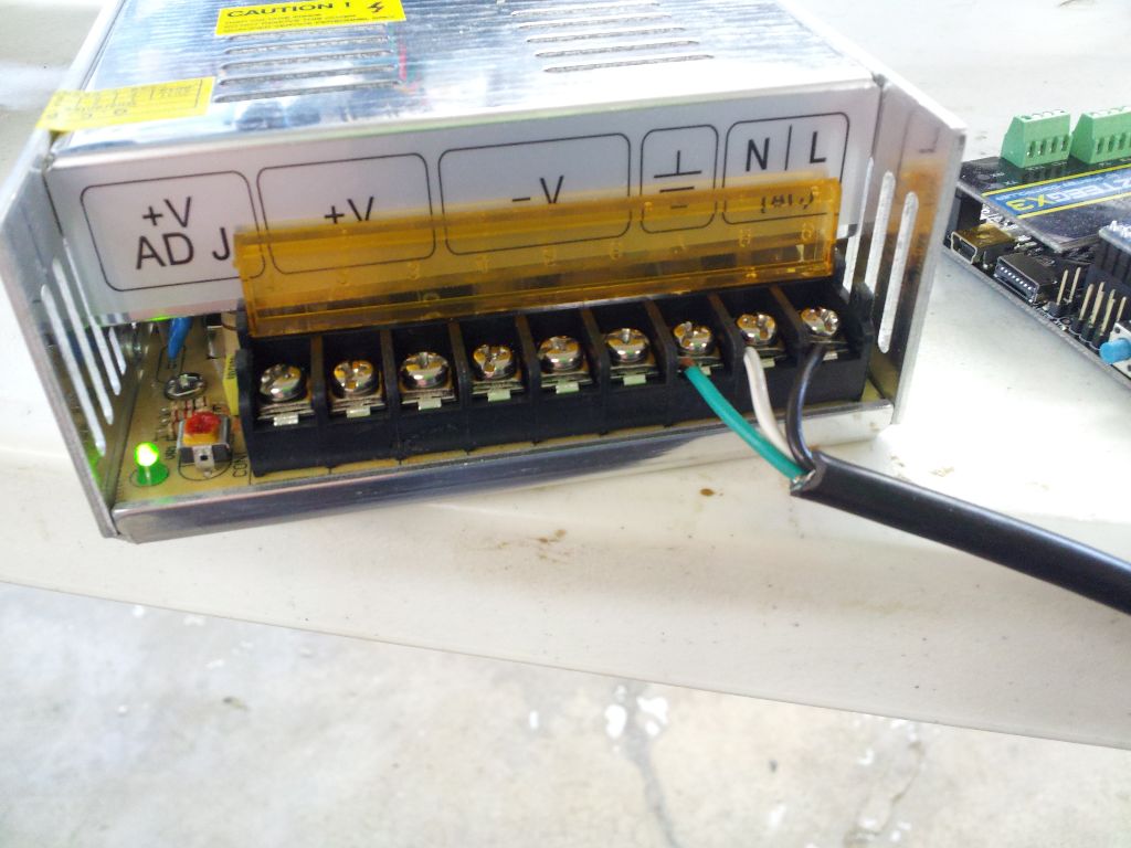
Finally it was time to wire up the power supply. I just chopped up an old IEC cable and screwed the terminals down.

A quick power on test of the azteeg.
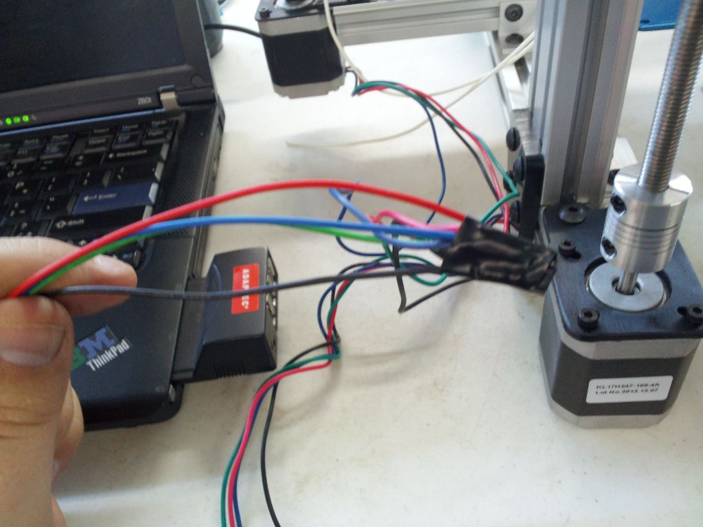
A little bit of wire twisting, some electrical tape and I loaded up Marlin firmware sketch, tweaked the values a little to match the azteeg x3. From here I ran into an issue where the board went into failsafe block mode because I don’t have any of the thermocouples hooked up it thought it was frying its self, so I disabled those in the firmware. Try #2, I was getting steps, but not good steps. I adjusted the stepper current using a meter and a small screwdriver on the pots, but still odd movement. I finally realized that I hadn’t put any jumpers on the microstepping selector and was doing full steps. After setting that it was moving like butter!
Here is a video of me just playing with the motor back and forth.
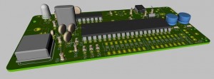
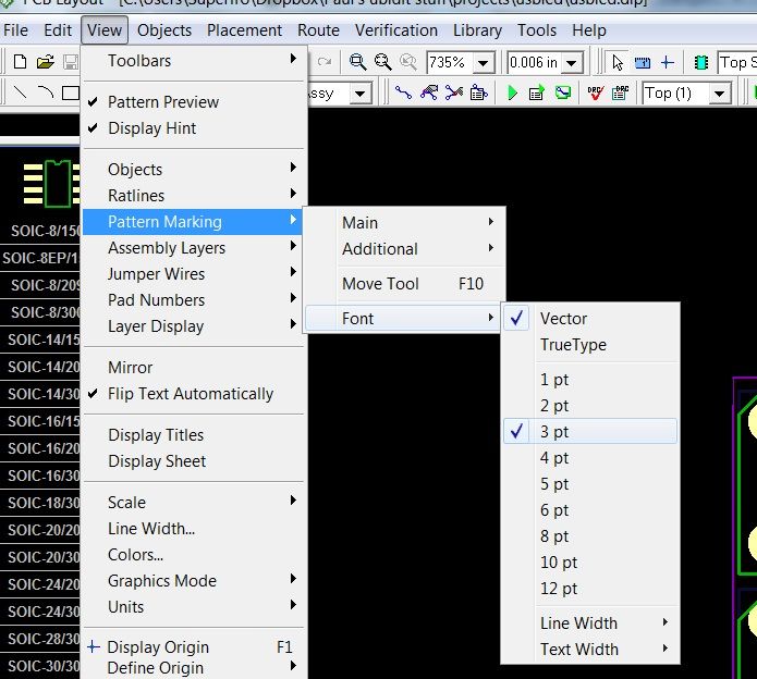 I’ve been using Dip Trace at home for making personal PCB’s for a few years now, it’s price and usability is pretty decent. So I thought I’d start by jotting down some tips for newcomers. This tip is dealing with reference designators, like U1, U2, R1, R2, etc… you know those markings that help you assemble your PCB.
First off you can change the font, size, and properties of a layout by going to View->Pattern Marking->Font. From there you can change to a True Type font, font size, and choose between bold and normal. It will apply to all ref’s in the current design.
The second one is to move the refdes. By hitting F10 while working, or going to View->Pattern Marking->Move Tool, You can then select your refdes and move it somewhere you can view it better. You can also rotate it while selected by hitting the ‘r’ key. These are handy when you have a lot of parts tightly squeezed together and want to be able to see the markings.
 I got some parts in for my ORD BOT 3d printer build and I spent a good day putting it together. Well I didn’t make as much progress as I anticipated and sadly had a pretty frustrating time, mostly with the QU-BD extruder build. While it should have been fairly straight forward let me start off by pointing out the build instruction flaws.
I’ve gotten a few requests for more info about my kit. So here is some more info until I finish writing the documentation:
Let me know if there is anything else I can comment on.
I always feel like its Christmas time when I get parts in the mail. So I got the power supply, the extruder, the stepper controller, drivers, and a bunch of other stuff that I may or may not need. I’ll post more pics and comments as I start to put it together, here’s some pics of what I got.


Here’s a quick video showing the streaming functionality. Right now there is no GUI on the host side, just a command line program that reads .ym files and streams them to the chip at 50hz.